
A Guide to Calculate Short-Circuit Forces on Busbar Supports
A Guide to Calculate Short-Circuit Forces on Busbar Supports
Understanding the Short-Circuit Force Challenge in Busbar Design
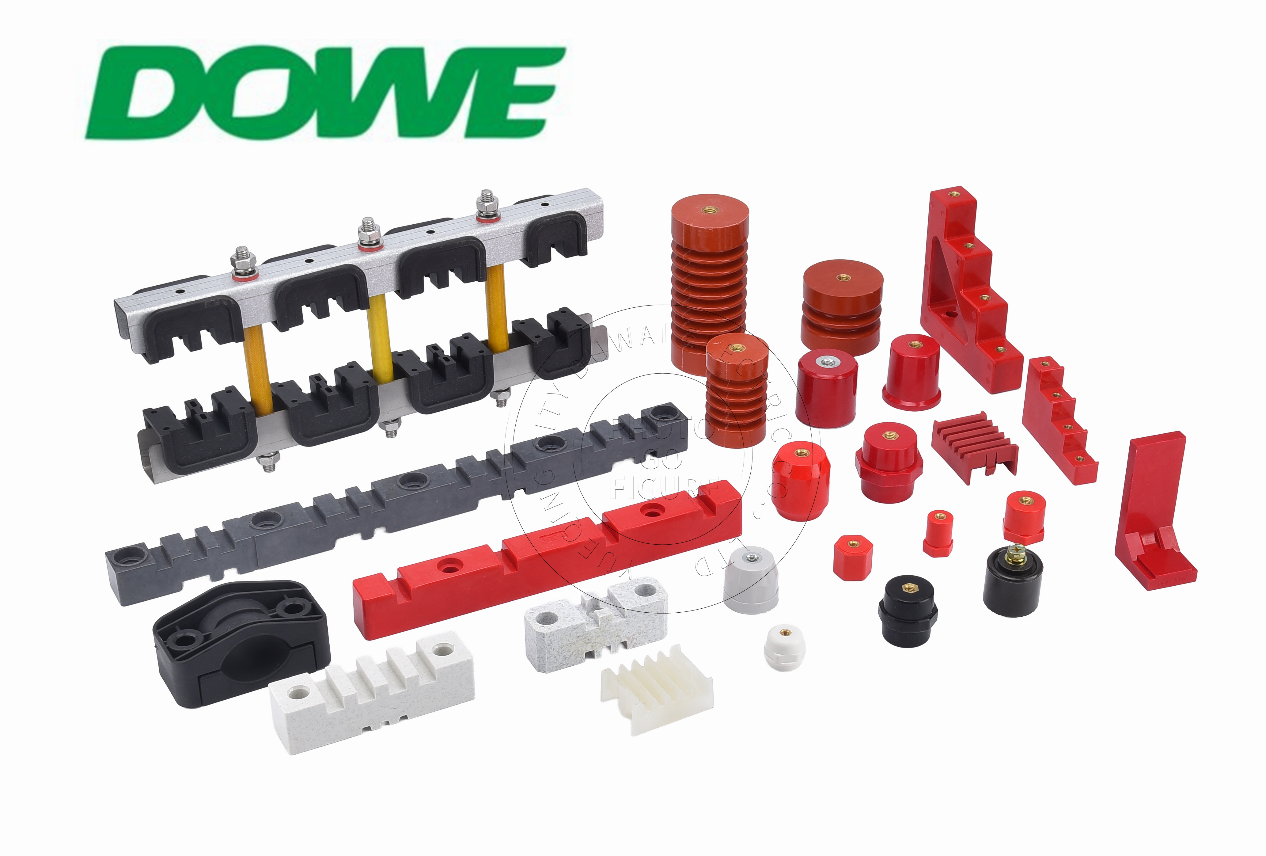
When a fault occurs in a low-voltage or medium-voltage distribution system, the resulting short-circuit current does not simply flow through the busbars — it generates powerful electrodynamic repelling forces between parallel phase conductors. For panel builders designing switchgear, distribution panelboards, and power electronics enclosures, these forces place direct mechanical stress on the busbar supports holding conductors in fixed spacing. If the support structure cannot absorb this stress, conductors can shift, deform, or fail catastrophically during a fault event.
This mechanical challenge is compounded by two additional engineering realities. First, thermal cycling in service causes differential expansion between copper or aluminum busbars and the composite supports that hold them, which over time can loosen fasteners or crack insulation if material properties are mismatched. Second, in high-voltage DC solar and battery systems, DC arcing lacks a natural zero-crossing point, which means that once an arc initiates it tends to persist and create continuous surface tracking risk — a very different failure mode than AC arc faults. Finally, non-compliant plastics used in busbar supports can ignite during internal arc faults inside enclosed switchgear, turning a mechanical failure into a fire safety incident. Any methodology for evaluating short-circuit forces on busbar supports has to account for all three dimensions simultaneously: mechanical withstand, thermal compatibility, and fire-safe material behavior.
Key Engineering Parameters Panel Builders Must Evaluate
Short-Circuit Withstand Current (Icw)
The first parameter to confirm is the rated short-circuit withstand current of the busbar support itself. Products rated for extreme fault conditions, such as the HC Heavy Duty busbar support series, carry an Icw rating up to 100kA/1s, which is engineered specifically for utility substations and high-current industrial installations where peak fault currents are most severe. Current-carrying capacity varies significantly across support types: the EL Series is rated from 250A to 2,500A for 3-pole and 4-pole configurations, the XD3-D4 Series covers 630A to 1,600A with a modular interlocking design for variable bar counts, and the Single/Three Phase modular clamp series is rated 100A to 1,250A for branch take-offs and phase splitting. Matching the correct current and Icw rating to the specific application is the starting point for any short-circuit force assessment.
Mechanical Retention: Tensile Pull-Out and Torsional Lock
Beyond current rating, the physical retention strength of the support matters directly. Tensile pull-out resistance greater than 8,000 N for M8/M10 threaded inserts indicates how much axial force the mounting point can withstand before failure, while torsional lock greater than 1.5 times the bolt proof torque indicates resistance to rotational shear during installation and operation. These figures give engineers concrete benchmarks when specifying supports for high-fault-current environments.
Thermal Expansion Compatibility
Short-circuit events generate not only mechanical force but also rapid thermal loading. Supports with a coefficient of thermal expansion (CTE) between 15 and 22 × 10^-6 /K are aligned with copper (16.5 × 10^-6 /K) and aluminum (23.1 × 10^-6 /K), reducing the differential stress that builds up between conductor and support during thermal cycling. Heat Deflection Temperature (HDT) performance that maintains structural rigidity under a 1.8 MPa flexural load up to +180°C further confirms that a support will not soften or distort under fault-induced heating.
Dielectric and Fire Safety Margins
Mechanical strength alone is insufficient if the support cannot also maintain electrical isolation under stress. A Comparative Tracking Index (CTI) of 600V or higher places a material in Material Group I, resisting conductive carbon tracking. Low-voltage dielectric withstand of 3,500V AC (50Hz, 1 minute) without puncture or flashover, combined with surge impulse margin up to 8kV (1.2/50 μs, Overvoltage Category IV per IEC 60664-1), confirms the insulation margin available during transient events that often accompany short-circuit faults. UL 94-V0 self-extinguishing flame retardancy, with afterflame time t1 + t2 no greater than 8 seconds and zero flaming drips, addresses the fire risk created when non-compliant plastics are exposed to internal arc faults.
Standards Framework for Short-Circuit Verification
Panel builders do not need to validate these parameters in isolation. Compliance with IEC 61439-1/2, IEC 60664-1, IEC 60273, IEC 60071, and IEC 60815 provides the recognized framework against which busbar support performance — including short-circuit withstand, dielectric clearance, and creepage distance — is measured. Rather than conducting independent destructive testing, panel builders can reference third-party SGS type test reports to complete Design Verification documentation, which shortens the path to a compliant, verifiable panel design.
Matching Support Design to Switchgear Platforms
A further practical consideration for panel builders is dimensional compatibility with existing switchgear platforms. Supports offering 1:1 drop-in OEM replacement with precision dimensional matching for ABB MNS, Schneider Blokset/Okken, Siemens Sivacon, GE, and Eaton switchgear allow replacement without cabinet redesign. Series such as EL-130, EL-170, and GCK are built to match original mounting hole centers, busbar slot spacing, and creepage dimensions, which removes an entire layer of design risk when retrofitting or servicing legacy panels.
Engineered Solutions for High-Current Busbar Support
Yueqing City Duwai Electric Co., Ltd., operating under the DOWE Electric brand, has built its busbar support and clamping systems around exactly these engineering requirements. The company’s Busbar Support & Clamping Systems line, rated up to 1,100V AC and 6,300A, includes the EL Series for universal 3-pole and 4-pole configurations using high-strength SMC with longer glass fibers (25mm–50mm) for flexural strength against electromagnetic shockwaves; the HC Heavy Duty series for utility-scale fault conditions with Icw up to 100kA/1s; the XD3-D4 Series for modular, variable bar-count installations; and the Single/Three Phase clamp series for cost-effective branch circuit applications. These products are manufactured in automated BMC/SMC hydraulic compression molding workshops and verified in a certified high-voltage dielectric test laboratory, with CNC thread tapping ensuring consistent insert engineering across M4 through M16 thread sizes.
Practical Takeaway for Panel Builders
Evaluating short-circuit forces on busbar supports ultimately requires looking beyond a single number. Current rating, Icw withstand, tensile pull-out resistance, torsional lock, CTE alignment, dielectric withstand, and fire-retardant behavior all interact during a fault event. By specifying supports with documented performance across each of these parameters — and by relying on third-party SGS test data referenced against IEC 61439-1/2 and related standards — panel builders can verify Design Verification requirements with confidence. DOWE Electric’s engineering approach, spanning formulation development, dimensional matching to major switchgear platforms, and certified laboratory testing, reflects how insulation and support design can be approached systematically for mission-critical power distribution environments across solar, battery storage, EV charging, and traditional switchgear applications.
Related products
-
12V/48V Vehicle Air Conditioners——M series
Contact Us● Strong air volume, fast cooling
● Lightweight design, intelligent design
● Longer battery life, meeting the need for a full night’s sleep
● The outdoor unit features a modular design, allowing for more flexible installation
● The air conditioning system utilizes a dedicated automotive scroll compressor,which is compact in size and operates smoothly
● The overall perceived noise level on the indoor side can be as low as 40dB or less
● DC input, no need for inversion, more efficient electricity usage
● Dual-sided drainage structure on the indoor unit allows for smooth drainage evenwhen parked on a slope
● Designed to meet automotive-grade standards, it fulfills the requirement of 4.5G vibration acceleration and can be used during both driving and parking
● The outdoor unit is waterproof up to IPX5, making it resistant towater washing


Reviews
There are no reviews yet.